Lab 3 · Digital I/O & Motors — Controlling the Motor
This lab adds the L293 motor driver chip and the motor to your setup. You will write a program that sets the motor's direction and speed.
Part 1 · Setting up the hardware
Today you have two chips to place instead of one: the MCP3008 (from Lab 2) and the L293 (new).
The wiring diagram
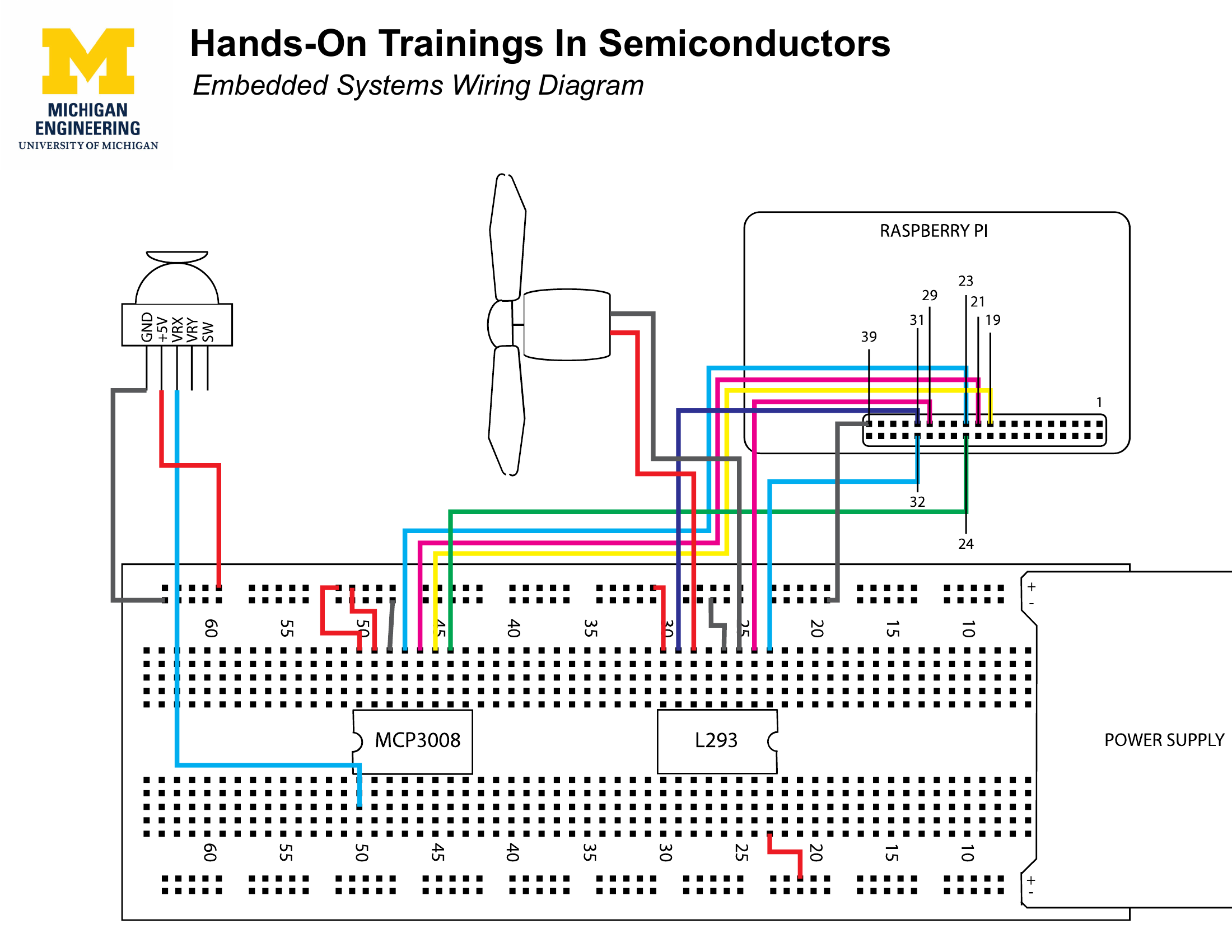
Step 1 · Place the chips
Put both chips on the breadboard, each straddling the center gap. The MCP3008 goes on the left and the L293 goes on the right (check the labels printed lightly on the chips).
Both chips have orientation marks
Each chip has a small semi-circular divot. Make sure both face the direction shown in the wiring diagram before you press them in.
Step 2 · Attach the power supply
The power supply board (from yesterday) connects to a battery this time. The motor needs more current than a USB cable alone can provide.
Step 3 · Wire everything up
Follow the wiring diagram. Wire positions matter; wire colors do not.
Part 2 · Programming the Motor
Step 1 · Open the file
Step 2 · Configure pin modes (setup function)
Find the line in setup() that says !!!! PUT YOUR SETUP CODE HERE !!!!.
Before the motor can move, the Pi needs to know which pins are outputs and what kind:
L293_ENABLEcontrols speed — it needs PWM output.L293_INPUT1andL293_INPUT2control direction — they need digital output.
Which function sets a pin's mode? What are the correct mode constants for each pin? → pinMode() · Pins & constants
Think about it
Why does L293_ENABLE need a different mode than the other two pins? What is the difference between OUTPUT and PWM_OUTPUT? → What is PWM? · The motor driver
Step 3 · Drive the motor (loop function)
Find the !!!! PUT YOUR LOOP CODE HERE !!!! line in loop(). You need to:
- Set the motor speed — use
pwmWrite()onL293_ENABLE.PWM_MAXVALis full speed. → pwmWrite() - Set the motor direction — use
digitalWrite()onL293_INPUT1andL293_INPUT2. The two direction pins must always be opposite values. → digitalWrite() · The motor driver - Add a delay — so the motor runs for a visible amount of time. → delay()
Try it
If the motor spins the wrong direction, what is the smallest change to your digitalWrite() calls that would reverse it?
Step 4 · Build and run
The motor (with the fan blade) should spin. If it does not, check Troubleshooting.
Step 5 · Challenge
Try it
Modify your program so the motor:
- Spins one direction for 5 seconds.
- Stops and spins the other direction for 5 seconds.
- Then slows to 60% speed and keeps spinning at that forever.
Hints: you will need delay() for timing, and a fraction of PWM_MAXVAL for the final speed. Think about what 60% of PWM_MAXVAL looks like in code — and how if/else or multiple blocks can sequence the behavior. → delay() · pwmWrite()
Bonus · Joystick controls the motor
What if the joystick controlled the motor's speed and direction, instead of hard-coded values?
The joymotor.c file in your repo is a completed example of exactly this. Study how it works — do not copy it line for line. Notice how it reads a value from the joystick and uses that to set the motor. How does it handle the fact that analogRead() returns 0–1023, but the motor direction expects only HIGH or LOW? → Scaling numbers